3.3.1. Survey File
Survey files provide the survey information for predicting data with dcipoctree_fwd.exe. Whether DC and/or IP are being simulated, the format is the same. The general format for predicted data files is shown below.
Note
The [ ] brackets are used for columns are not always required. For surface formatted files, the Z values are omitted. For general formatted files, the Z values must be included.
where
IPTYPE line is used only when simulating IP data. Set IPTYPE=1 for apparent chargeability and set IPTYPE=2 for secondary potential
\(X_A(i) \;\;\; Y_A(i) \;\;\; [Z_A(i)]\) is the Easting, Northing and vertical (if needed) position of the A-electrode for source \(i\).
\(X_B(i) \;\;\; Y_B(i) \;\;\; [Z_B(i)]\) is the Easting, Northing and vertical (if needed) position of the B-electrode for source \(i\).
\(X_M(i,j) \;\;\; Y_M(i,j) \;\;\; [Z_M(i,j)]\) is the Easting, Northing and vertical (if needed) position of M-electrode associated with source \(i\) and receiver \(j\).
\(X_N(i,j) \;\;\; Y_N(i,j) \;\;\; [Z_N(i,j)]\) is the Easting, Northing and vertical (if needed) position of N-electrode associated with source \(i\) and receiver \(j\).
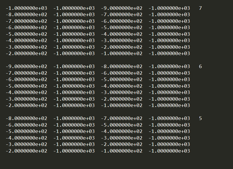
3.3.1.1. Example 1: Dipole-Dipole Surface Data
For electrodes defined only on the surface, the vertical location is determined by the topography. As a result, columns for the vertical position of each electrode are not required. Below, we see the format for the survey file. In this case, there are two sources, each with a different number of receivers.
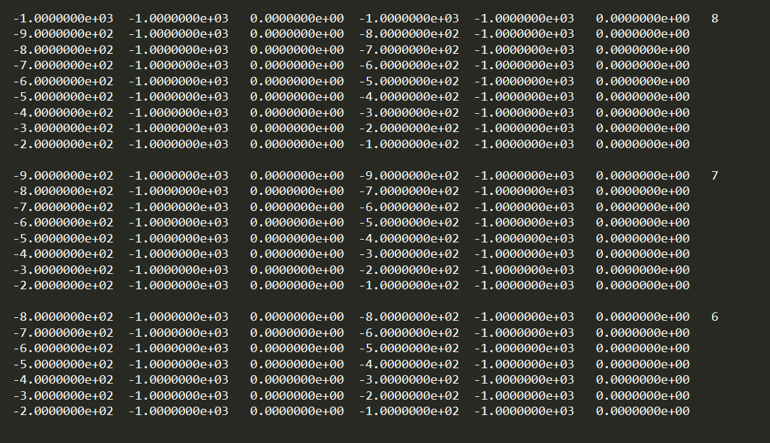
3.3.1.2. Example 2: Pole-Dipole Data with General Format
For the general data format (surface and/or borehole), the vertical locations of the electrodes are defined. Below, we see the format for the surface file. Since the sources are pole sources, we see that the locations of the A and B electrodes are identical. If the receivers were poles, the M and N locations of corresponding M and N electrodes would be identical.