5.2.3. Forward Modeling
Here, the code dcipoctree_fwd.exe and the input file dcip_fwd.inp (see format) are used to forward model DC and IP data along 9 pole-dipole profile lines oriented West to East. Files relevant to this part of the example are in the sub-folder fwd. For this example, we use the models that were created in the example “create model”. Before running this example, you may want to do the following:
To forward model the data, the following input file was used. Because the original survey file (survey_xyz.loc ) used the general format, we instead define the electrode locations in the forward modeling with data_Z.txt . The file data_Z.txt was output by create_octree_mesh_dcip.exe and projects all electrodes located in air cells to the discretize surface topography.
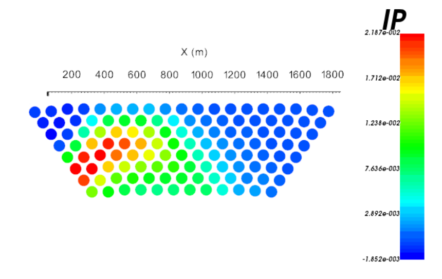
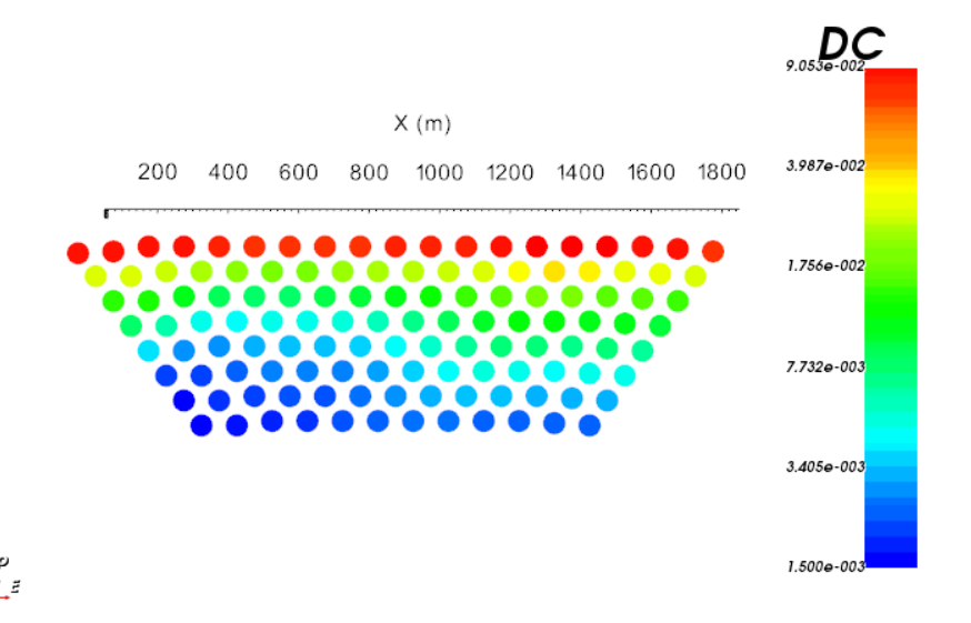
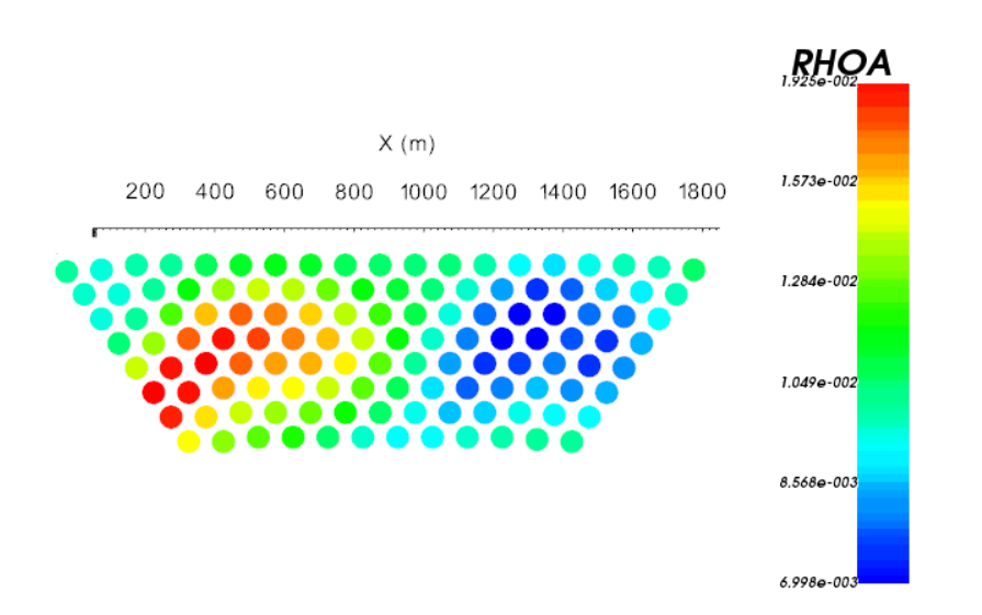
By choosing the IPL flag on the first line of the input file, we are modeling DC and IP data. And a linearized formulation for modeling the IP data is used. The DC data are the measured voltage normalized by the transmitter current (V/A). The code also outputs the corresponding apparent resistivity values. The IP data are the IP voltage normalized by the DC voltage (V/V). Below, we show the 2D pseudo-sections for data collected along profile line 5 (Northing = 0 m).
Voltage Data (V/V)
Apparent Resistivity (Ohm m)
Apparent Chargeability (V/V)