3.1.2. Tensor mesh file
This file contains the 3D mesh, for example mesh.msh, which defined the model region. Standard 3D mesh files have the following structure:
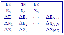
- \(NE\)
Number of cells in the East direction.
- \(NN\)
Number of cells in the North direction
- \(NZ\)
Number of cells in the vertical direction
- \(E_o, N_o, Z_o\)
Coordinates, in meters, of the southwest top corner, specified in (Easting, Northing, Elevation). The elevation can be relative to a reference elevation other than the sea level, but it needs to be consistent with the elevation used to specify the locations, observations, and topography files.
- \(\Delta E_n\)
\(n^{th}\) cell width in the easting direction (ordered W to E).
- \(\Delta N_n\)
\(n^{th}\) cell width in the northing direction (ordered S to N).
- \(\Delta Z_n\)
\(n^{th}\) cell thickness (ordered top to bottom).
The mesh can be designed in accordance with the area of interest and the spacing of the data available in the area. In general, the mesh consists of a core region which is directly beneath the area of available data, and a padding zone surrounding this core mesh. Within the core mesh, the size of the cells should be comparable with the spacing of the data. There is no restriction on the relative position of data locations and nodal points in the horizontal direction. The cell width in this area is usually uniform (this becomes important for converting from a standard mesh to an octree mesh).
The maximum depth of the mesh used for inversion should be large enough so that conductive/chargeable material below that depth does not produce a noticeable anomaly with the length scale covered by the data area. A rule of thumb is that the maximum depth should be at least half of the longest side of the data area. Based upon the user’s knowledge of the survey area, one may adjust the maximum depth as necessary. The cell thickness in vertical direction usually increases slightly with depth. In the shallow region, the ratio of thickness to width of about half is good, especially when surface topography is present. At depth, a cell thickness close to the cell width is advisable. Once this core mesh is designed, it can be extended laterally by padding with a few cells, possibly of variable width. This padding is necessary when the extracted anomalies are close to the boundary of the core mesh or if there are influences from anomalies outside the area which cannot be easily removed. Problems with more than 1,000,000 model cells, and/or more than a few thousand data points would be considered large, and can be expected to require a considerable amount of computing memory and time.
The vertical position of the mesh is specified in elevation. This is to accommodate the inversion of a data set acquired over a topographic surface. When there is strong topographic relief, which the user wishes to incorporate it into the inversion, special care should be taken to design the mesh. A conceptually simple approach is first to design a rectangular mesh whose top (specified by \(Z_o\)) is just below the highest elevation point, and then to strip off cells that are above the topographic surface. This is the approach taken in DCIPoctree. The number of cells to be stripped off in each column is determined by the user-supplied topography file. Only the remaining cells will be used in the forward modelling or included in the inversion as model parameters.
3.1.2.1. Example
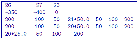
This example shows a mesh that consists of 26 cells in easting, 27 cells in the northing, and 23 cells in the vertical directions. The top of the mesh is located at 0 m of elevation and the southwest corner is at -350 m easting and -400 m northing. The cells in the core portion of the mesh are all 50 m \(\times\) 50 m \(\times\) 25 m. There are three cells in the padding zone in every direction except the top of the core mesh.